Winch Motor Continuous Duty Reversing Solenoid Dc Contactor Relay Switch Wiring Diagram
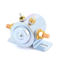
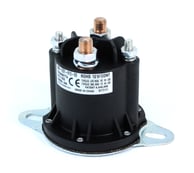
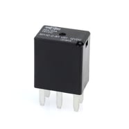
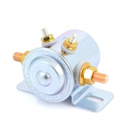
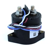
Relays, solenoids, and contactors are all switches—whether electro-mechanical or solid state—but there are critical differences that make each suitable for different applications. In this article, we will explain how each of these devices work and discuss some key selection considerations. Relays One of the most common electro-mechanical switches in a vehicle, the main job of a relay is to allow a low power signal (typically 40-100 amps) to control a higher-powered circuit. It can also allow multiple circuits to be controlled by one signal—for example in a police car where one switch can activate a siren and multiple warning lights at the same time. Relays come in a host of designs, from electromagnetic relays—which use magnets to physically open and close a switch to regulate signals, current, or voltage—to solid-state, which use semiconductors to control the flow of power. Because solid state relays have no moving parts, they are generally more reliable and have a longer service life. Unlike electro-magnetic relays, solid state relays are not subject to electrical arcs that can cause internal wear or failure. The six common footprint sizes of relays are: Shown at right: Example of a Mini ISO relay . Solenoids Solenoids are a type of relay engineered to remotely switch a heavier current (typically ranging from 85-200 amps). In contrast to the smaller electromechanical cube relays, a coil is used to generate a magnetic field when electricity is passed through it, which effectively opens or closes the circuit. The terms "solenoid" and "relay" can often be used interchangeably; however, in the automotive Some common applications for solenoids include vehicle starters, winches, snowplows, and electrical motors. A primary advantage of solenoids is their ability to use a low input to generate a larger output via the coil, thus reducing strain on the battery. Contactors The contactor is the relay to use when a circuit must support an even heavier current load (typically 100-600 amps). With voltage ratings from 12V DC up to 1200V DC, contactors are a cost-effective, safe, lightweight solution for DC high-voltage power systems. Common applications include industrial electric motors used in heavy trucks and equipment, buses, emergency vehicles, electric/hybrid vehicles, boats, light rail, mining, and other systems that simply require too much power for a standard relay or solenoid. Contactors typically have an integrated coil economizer to reduce the power required to hold the contacts closed, which helps increase system flexibility and reliability. They are often available with optional auxiliary contacts. SELECTION CONSIDERATIONS Current and Form Factor In terms of carrying capacity, relays are at the low end, followed by solenoids, then contactors at the highest point. While contactors can handle enough current to help power heavy equipment, they also come with the highest price tag and require the most space, whereas relays require little space and can be purchased very inexpensively. At 85-200 amps, many solenoids tend to fall right in the middle of these two, both in terms of carrying capacity and price. When determining which one of these three switching products is right for your design, consider the form factor. Typically, greater carrying capacity equals bigger size, so carefully note the amount of space available to ensure the device you need will fit. If there is a conflict, it is time to either rethink your design layout or scale back the electrical system. Ambient Environment When selecting any switching device, also consider the demands placed by the environment in which the device will reside. If protection from elements such as humidity, submersion, dust, and vibration is needed, then a sealed product is necessary. Look at the Ingress Protection (IP) rating to determine the specific protection offered. Operating temperature is another critical point. The engine and surrounding components can generate extreme temperatures as high as 175°F, so all neighboring devices must be rated accordingly. Continuous vs. Intermittent Ratings It is important to note that solenoids and contactors are rated for either continuous or intermittent use. Intermittent refers to applications that have a brief activation period alternated with a longer rest time, such as a starter switch. On the other hand, switching products with a continuous rating can support applications requiring continual run time, such as winches. One commonly asked question is whether one can use a continuous duty solenoid in place of an intermittent duty solenoid.While we always recommend using the component designed for the job, technically a continuous duty solenoid could be used but is in excess of what is needed. However, under NO circumstances can an intermittent duty solenoid be used when a continuous duty solenoid is required, as it is simply not equipped to handle a continuous demand. Choosing a Switching Device The decision to use a relay, solenoid, or contactor largely comes down to the current carrying capacity needed, while also considering how the form factor will fit into your design footprint. Once you have identified which of these three types of switching products is right for your needs, taking critical requirements like operating temperatures and other environmental demands into consideration will help you further narrow down your choices. To find the right switching device for your needs, check out our complete selection of relays, solenoids, and contactors . Here are a few top picks: 
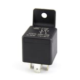 relays mentioned above but providing roughly the equivalent level of performance and featuring an ISO 280 footprint pin size and arrangement. They are designed to fit into typical ATM fuse boxes, power distribution units and holders.
 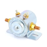 market, the term solenoid generally refers to a "metal can" type, whereas a relay typically refers to the standard "cube" style relay.
Topics: Resources & Tools, Buying Guides, Relays
Source: https://info.waytekwire.com/blog/relays-vs-solenoids-vs-contactors-a-comparison
Post a Comment for "Winch Motor Continuous Duty Reversing Solenoid Dc Contactor Relay Switch Wiring Diagram"